Plant utility planning
Water Bottling Line Utility Requirements
Plan electrical power, compressed air, PET blowing air, cooling, process water, drainage and ventilation before approving a complete water bottling line quotation.
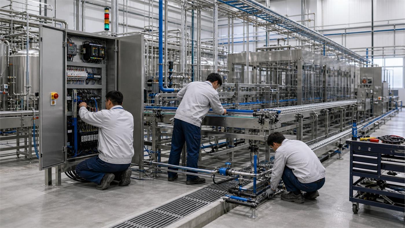
Utilities Must Match the Approved Production Basis
Utility demand cannot be copied from another project. Bottle format, line speed, water treatment, PET blowing, packing method, ambient conditions and operating schedule all change the plant requirement.
- Electrical load by machine and operating mode
- Low- and high-pressure air kept distinct
- Water, cooling and drainage connection schedule
- Buyer-supplier responsibility at every connection
Six Utility Systems to Define Before Purchase
Ask for a coordinated utility schedule after the equipment and bottle basis are approved. The schedule should distinguish connected load, normal demand, peak demand and buyer-side infrastructure.
Electrical power
Confirm voltage, frequency, phase, connected load, operating load, startup demand, control power and local panel responsibilities.
Low-pressure compressed air
Identify pneumatic valves, actuators, packers and instruments, including flow, pressure, quality, receiver and dryer assumptions.
PET blowing air
If bottles are blown in-house, treat high-pressure clean dry air as a separate engineered system tied to bottle, mold, blower and output.
Cooling and heat rejection
Confirm whether machines use air cooling, chilled water or cooling water and how heat leaves the room.
Water supply and process piping
Separate source water, treatment feeds, product water, cleaning water and any cooling circuits, with quality and connection requirements.
Drainage and ventilation
Plan wet-area drainage, wastewater route, room temperature, humidity, noise and ventilation around treatment, compressors and production equipment.
Utility Information the Supplier Should Provide
Use one schedule for the complete line so local engineers can size infrastructure from approved machine data rather than assumptions.
| Utility item | Supplier should state | Buyer should confirm |
|---|---|---|
| Electrical | Connected and normal load, voltage, frequency, phase, connection point and panel scope. | Available supply, transformer and distribution capacity, local code and installation route. |
| Low-pressure air | Required pressure, flow, air quality, dryer and receiver basis. | Compressor room, pipe route, ambient conditions and local installation. |
| High-pressure PET air | Blower-specific pressure, flow, quality, storage and cooling basis. | Bottle range, output, compressor location, noise and high-pressure piping responsibility. |
| Cooling | Heat load, supply and return conditions, water quality or ventilation requirement. | Ambient design conditions, chiller or tower location and pipe route. |
| Water | Flow, pressure, quality, temperature and connection point for every use. | Source capacity, storage, treatment, local piping and sanitation plan. |
| Drainage | Expected discharge points and operating or cleaning basis. | Floor levels, drain capacity, wastewater route and local environmental requirements. |
Record the Condition Behind Every Utility Figure
A utility number is usable only with its unit, operating condition and connection boundary. Ask whether the figure is connected load, normal running demand, a peak, a startup condition or a measured consumption over a period.
For air, record the flow reference conditions and whether the stated flow is normalized or actual, together with pressure and the required quality at the point of use. For cooling, record the supply and return conditions and the relevant ambient basis. Do not compare values that use different reference conditions.
Ask the supplier and the qualified site designer to identify which loads operate together and which duty cases govern infrastructure. Keep process water, cleaning supply, cooling circulation and rejected water on separately identified connections. A filler product-flow figure alone is not the whole factory water requirement.
Use One Row per Utility Connection
Give each connection a stable ID that appears on the layout and utility schedule. Record the machine, service, unit and reference basis, normal and peak condition, connection location, supplier data revision, responsible party and confirmation status.
At site review, compare the required condition with an identified measurement or supply record at the agreed point. Keep missing information open until the responsible designer and supplier have resolved it; do not silently turn a preliminary allowance into an approved installation value.
| Connection record | What to write | Status evidence |
|---|---|---|
| ID and location | Machine ID, service and drawing coordinate | Coordinated layout and connection list. |
| Demand basis | Unit, reference conditions, normal/peak/startup mode | Supplier schedule with revision and assumptions. |
| Available supply | Condition at the agreed connection point | Identified measurement or approved site record. |
| Ownership and closure | Supplier connection, buyer distribution, open item and owner | Written confirmation before design release. |
FAQ
What utilities does a water bottling line need?
A complete plant may need incoming water, electrical power, low-pressure compressed air, high-pressure air for PET blowing, cooling, drainage and ventilation. The final utility schedule must come from the approved equipment list and operating basis.
How should I calculate the electrical load for a bottling plant?
Ask each supplier for connected load and normal operating load by machine, then review simultaneous operation, startup demand, voltage, frequency, phase, local electrical rules and a suitable design margin with a qualified local electrical professional.
Does PET bottle blowing need a separate high-pressure air system?
PET blowing commonly needs clean, dry high-pressure air, while valves and other pneumatic equipment may use lower pressure air. Required pressure, flow, air quality, receiver, dryer and cooling depend on the selected blower, bottle and output.
What water connections should be included in the utility plan?
Separate raw-water supply, treatment feeds, cleaning water, cooling-water circuits where required and product-water piping. Confirm pressure, flow, quality, connection size, temperature and responsibility for each connection.
How should drainage be planned around a water bottling line?
Place hygienic, accessible drainage near wet-process and cleaning areas without creating standing water or unsafe traffic. Drain capacity, slope, materials and wastewater handling must follow the actual process and local requirements.
Do compressors and blowing machines require cooling or ventilation?
Requirements vary by equipment. The supplier should state heat rejection, cooling-water or air-cooling needs, ambient limits and service clearance so the buyer can design the utility room and ventilation correctly.
Who supplies local utility piping and cables?
The quotation should identify machine-side connection points and clearly divide supplier work from buyer-side transformers, panels, cables, trays, pipes, valves, drains, supports and local installation labor.
What should a supplier utility schedule contain?
Request one coordinated schedule listing each machine, utility type, connection point, pressure or voltage basis, flow or load, quality requirement, normal and peak demand, and whether the item is supplier-supplied or buyer-side.
Verify utilities at realistic load before final line selection
Utility planning should show quality, pressure, flow, peak demand and connection points. Nameplate totals alone do not expose startup peaks, simultaneity or process-quality requirements.
Allot Tech Project Desk · Mr KcalBuyer-education content prepared for project clarification. Final equipment scope, engineering values, prices and guarantees must be confirmed in a supplier's written proposal.Updated:
Request a Water Bottling Line Utility Review
Share what you know now. The goal is to prepare a useful plant brief before a machine quotation is built.