utilities planning question
How should a cooling-water loop be planned for a bottling line?
Cooling-water design must match each user’s flow, temperature, pressure, quality and operating pattern, then include generation, pumps, distribution, buffering, treatment and monitoring. Do not size from one machine label alone.
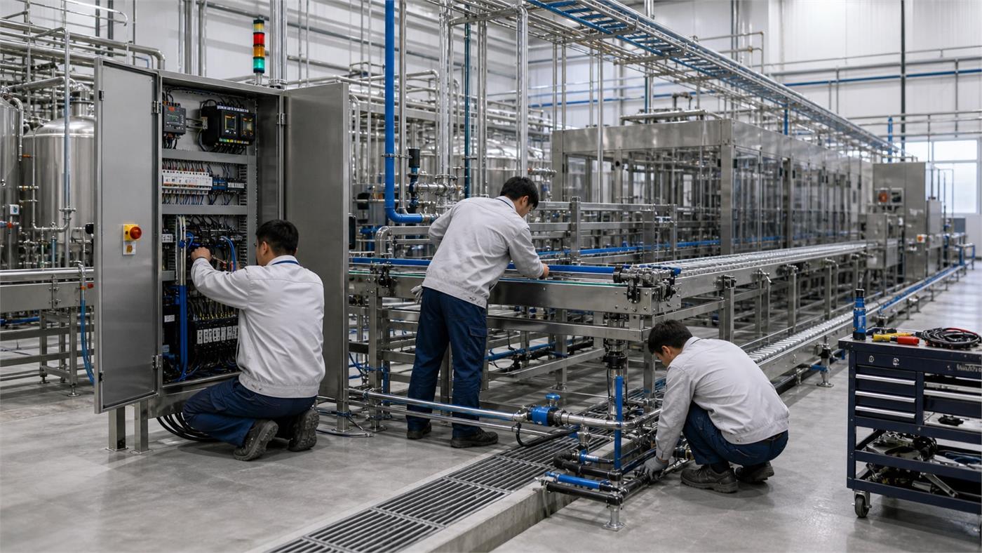
Bottling Line Cooling-Water Loop
Cooling-water design must match each user’s flow, temperature, pressure, quality and operating pattern, then include generation, pumps, distribution, buffering, treatment and monitoring. Do not size from one machine label alone. Use the checklist below to turn the question into a supplier-ready decision without relying on universal figures or unverified claims.
- Equipment list
- Factory climate
- Operating schedule
- Future expansion
Decisions Behind Bottling Line Cooling-Water Loop
Define these items against the real product, package, site and production plan before comparing equipment or supplier proposals.
User schedule
Collect supplier conditions at every connection
Load diversity
Model simultaneous and changing demand
Distribution
Check pressure loss, balance and isolation
Water quality
Define treatment, cleaning and monitoring
Bottling Line Cooling-Water Loop Supplier Evidence Matrix
Use the matrix to separate buyer inputs, supplier commitments and evidence that can be checked during design review, FAT, installation or operation.
| Decision | What to define | Evidence to request |
|---|---|---|
| User schedule | Collect supplier conditions at every connection | Cooling-user schedule |
| Load diversity | Model simultaneous and changing demand | Heat-load and hydraulic calculation |
| Distribution | Check pressure loss, balance and isolation | Piping and instrumentation diagram |
| Water quality | Define treatment, cleaning and monitoring | Water-quality and maintenance plan |
Project Inputs for Bottling Line Cooling-Water Loop
Incomplete inputs force suppliers to make assumptions. Mark unknown items openly and assign the next action instead of hiding the gap.
Equipment list
Provide current, project-specific information for bottling line cooling water system so the supplier can state assumptions and remaining decisions.
Factory climate
Provide current, project-specific information for bottling line cooling water system so the supplier can state assumptions and remaining decisions.
Operating schedule
Provide current, project-specific information for bottling line cooling water system so the supplier can state assumptions and remaining decisions.
Future expansion
Provide current, project-specific information for bottling line cooling water system so the supplier can state assumptions and remaining decisions.
FAQ
How should a cooling-water loop be planned for a bottling line?
Cooling-water design must match each user’s flow, temperature, pressure, quality and operating pattern, then include generation, pumps, distribution, buffering, treatment and monitoring. Do not size from one machine label alone.
Which inputs are needed for bottling line cooling water system?
Start with Equipment list, Factory climate, Operating schedule, Future expansion. The selected supplier and qualified local specialists must confirm the final project basis.
What evidence should a supplier provide for bottling line cooling water system?
Request Cooling-user schedule, Heat-load and hydraulic calculation, Piping and instrumentation diagram, Water-quality and maintenance plan. Compare evidence against the same approved product, package, capacity and site conditions.
What is a common mistake when planning bottling line cooling water system?
A common mistake is accepting a generic answer without defining the actual bottle, product, output, utilities, interfaces and acceptance method for the project.
How does bottling line cooling water system connect to a complete water bottling line?
It affects adjacent equipment, controls, utilities, layout, quality checks or operating responsibilities. Record those interfaces in the complete-line scope and responsibility matrix.
Planning calculator: Bottling line cooling water
Enter measured or explicitly assumed values. Keep the units and measurement boundary consistent. Compare a second scenario before choosing equipment.
Equation and scope
A × 60 ÷ (4.186 × B)
- A: Heat load [kW]
- B: Temperature rise [K]
⌈x⌉ rounds upward and ⌊x⌋ downward to a whole count. min/max select the lowest/highest sample. ∉ means outside the stated interval.
Cooling-water flow follows the heat transferred and the permitted supply-to-return temperature rise. Use the load at the relevant operating condition. Chiller capacity, water quality and pump head remain separate selections.
Worked example: editable assumptions
Record assumptions separately from measurements. The example numbers demonstrate arithmetic and are not a recommended equipment specification.
| Input or result | Value | Unit |
|---|---|---|
| A — Heat load | 40 | kW |
| B — Temperature rise | 5 | K |
| Flow | 114.66794 | L/min |
Your project inputs
Calculated result
| Input or result | Value | Unit |
|---|---|---|
| Flow | 114.66794 | L/min |
This is a planning estimate from the stated inputs, not a machine guarantee or design approval.
Calculation stays in this browser; this worksheet sends no project inputs to the server.
Before procurement, ask the responsible specialist to review the assumptions, drawings and test evidence. A valid calculation does not mean a project has passed acceptance.
Why does a smaller cooling-water temperature rise need more flow?
These are invented teaching inputs, not equipment ratings, market prices or an accepted tolerance. The two scenarios change one assumption while holding the other inputs constant. Use the comparison to identify what must be measured or agreed for your project.
Read both inputs and outputs in the stated units. The input register explains what evidence to request before substituting your own values. If a source is missing, record the uncertainty rather than silently entering zero or accepting a supplier estimate as a measurement.
Changed assumption: Temperature rise
Input assumptions
| Record item | Unit | Scenario A | Scenario B |
|---|---|---|---|
| Heat load | kW | 48 | 48 |
| Temperature rise | K | 6 | 4 |
Calculated comparison
| Record item | Unit | Scenario A | Scenario B |
|---|---|---|---|
| Flow | L/min | 114.6679 | 172.0019 |
What the comparison means
The example keeps heat duty constant and reduces the supply-to-return temperature rise. More water must then carry the same heat away. The resulting flow is not a pump specification: circuit pressure losses, water condition and available temperatures remain unresolved. If actual heat duty changes by operating mode, prepare a separate case for each relevant mode.
How to establish this input
| Record item | How to establish this input |
|---|---|
| Heat load | Retain the material or fluid identity, operating condition, declared reference basis and source for the load, property or dose. Check whether a supplier value is measured, specified or assumed before applying it to the actual process. |
| Temperature rise | Retain the material or fluid identity, operating condition, declared reference basis and source for the load, property or dose. Check whether a supplier value is measured, specified or assumed before applying it to the actual process. |
Evidence to request
Request the heat-duty boundary, supply and return conditions, water or fluid composition, pressure-loss information and confirmation of which loads can operate simultaneously.
Project decision record
| Record item | Project decision record |
|---|---|
| Input assumptions | Identify the bottle, pack or material configuration, operating mode and measurement boundary. State the start and finish of the observation and which accepted output the comparison represents; unlike boundaries cannot establish a performance improvement. |
| How to establish this input | Mark every input as measured, taken from a drawing, quoted or assumed. Retain the source document identifier, revision, date and responsible person. The same numeral with a different unit or data status is not automatically a comparable input. |
| Project decision record | Ask the responsible supplier and buyer to agree actual acceptance criteria and the evidence that will demonstrate them. Teaching values and calculated outputs on this page do not become approved operating settings or contractual performance guarantees. |
| Evidence to request | Record the decision affected by the result, the measurement or trial still needed, its owner and the next review. Keep unresolved items visible in the handover file instead of changing the figures to make a preferred equipment option appear acceptable. |
Why does a smaller cooling-water temperature rise need more flow?
The estimate holds the declared heat duty constant while changing water temperature rise. A lower rise therefore increases calculated flow. It does not establish pump head, chiller selection or heat-exchanger performance. Identify the actual inlet and outlet measurement points before comparing the two readings.
Which inputs should you verify before using this result?
These are hypothetical sensitivity examples, not measurements from a factory. The lower and higher inputs are chosen for teaching; they are not equipment limits, approved settings, uncertainty intervals or recommended allowances. Whole-count and bounded inputs are adjusted to keep the examples valid, so the changes are not all the same percentage.
Read one input row at a time. For its lower and higher result, only that named input changes; every other input remains at the baseline shown in the first table. Do not combine all the lower columns or all the higher columns into a single operating scenario: those combined conditions have not been calculated here.
Baseline and selected input changes
| Input being changed | Unit | Lower input | Baseline input | Higher input |
|---|---|---|---|---|
| Heat load | kW | 38.4 | 48 | 57.6 |
| Temperature rise | K | 4.8 | 6 | 7.2 |
Output when one input changes
| Input being changed | Calculated output | Lower input | Baseline input | Higher input |
|---|---|---|---|---|
| Heat load | Flow (L/min) | 91.7344 | 114.6679 | 137.6015 |
| Temperature rise | Flow (L/min) | 143.3349 | 114.6679 | 95.5566 |
Interpret this problem
A one-input comparison isolates the arithmetic effect inside this model. It does not establish that the input can change independently on a real line. If two quantities share the same measurement, production period or physical constraint, ask the responsible supplier to review that relationship before changing the project basis.
Equal displayed results need interpretation. Whole-item outputs can remain unchanged until a rounding boundary is crossed; displayed decimal values can also hide a small change. Check the stated unit, the underlying counts and the specific explanation below before concluding that an input has no effect.
What to verify next
Use a surprising difference to choose the next measurement, rather than selecting whichever assumption gives the preferred answer. Record the input label and unit, its measured or assumed status, document revision, operating condition and who will verify it. Keep the original record so a later reader can reproduce the comparison.
For a supplier discussion, take the baseline, one changed input, the affected output and the unresolved question together. Agree the field observation or controlled trial that can resolve it and record the responsible person. A mathematical change does not by itself approve equipment capacity, quality acceptance, installation or a purchase decision.
Where do the inputs come from, and which result do they change?
Mark each project value as measured, quoted, taken from a drawing, assumed or awaiting confirmation. Early estimates can use stated assumptions; a missing value is not zero. The calculator defaults are illustrative, not evidence about your plant.
| Input or result / Unit | Evidence to request | Substitution to avoid |
|---|---|---|
| Heat load (kW) | Request the heat-rejection schedule for the declared operating case, including which portion enters the room or cooling circuit. Keep the supplier reference and basis of estimate. | Installed electrical power is not automatically the heat released to this boundary. Heat exported in product, exhaust or another circuit must not be counted twice. |
| Temperature rise (K) | Name the same fluid stream at its upstream and downstream measuring points. Record both temperatures, timing and operating state behind the declared temperature rise. | An air-temperature difference and a water-temperature rise belong to different heat balances. Do not use ambient-to-product temperature difference in place of the specified stream rise. |
Input-to-result trace
The links below trace each input to the equations that use it. They describe mathematical dependence, not every shared input-validation rule. Retain the source, revision, operating condition and person responsible for each value before comparing offers.
Heat load (kW) → Flow (L/min)
Temperature rise (K) → Flow (L/min)
Equations and unit basis
Use the numerical input values in the units shown here. Conversion factors belong to these units. Compare the equation with the calculator result and the example before transferring it to another unit system.
Flow (L/min)
Flow (L/min) = ((Heat load × 60) ÷ (4.186 × Temperature rise))
Inputs used in this result: Temperature rise (K); Heat load (kW).
ceil rounds up to a whole count; floor rounds down. min and max select the smallest and largest values. I(P) is 1 when condition P is true, otherwise 0; ∨ means “or”. π is the circle constant. Semicolons separate function arguments.
The constants below are reference assumptions in this model. Confirm their suitability for the fluid, temperature or load case; they are not measured project properties. cₚ = 4.186 kJ/(kg·K).
These relations explain the planning model. A mathematical result does not set acceptance limits, approve a machine setting or establish legal filling tolerances. Keep project approval and evidence separate from arithmetic.
Heat load + Temperature rise: What happens when two planning inputs change together?
Compare four explicitly hypothetical combinations. Only the two named inputs vary; every other input remains fixed. These examples complete the corner cases around the single-input comparisons above. They are teaching assumptions, not measured plant data, recommended settings, approved limits or probability ranges.
Read A as lower/lower, B as lower/higher, C as higher/lower and D as higher/higher, in the displayed input order. A is the comparison origin, not the original project baseline. The two factors are varied independently for this calculation; that does not prove every combination is physically feasible.
A numerator increase and denominator increase can partly offset each other. Compare all four combinations rather than inferring the result from two equal percentages.
Calculated results across the four cases
| Calculated result | A | B | C | D |
|---|---|---|---|---|
| Flow (L/min) | 114.667941 | 76.445294 | 172.001911 | 114.667941 |
Separate and combined changes from A
| Calculated result | Input or result | Calculated value |
|---|---|---|
| Flow (L/min) | First input alone: C − A | 57.33397 |
| Flow (L/min) | Second input alone: B − A | -38.222647 |
| Flow (L/min) | Both inputs: D − A | 0 |
| Flow (L/min) | Sum of the two separate changes | 19.111323 |
| Flow (L/min) | Combined change minus that sum | -19.111323 |
The last difference is D − C − B + A, in the output unit. Zero means the four computed values are additive at these selected points; it does not prove independence in a real line. A nonzero difference can follow from multiplication, division or whole-count rounding. It is not a measured machine interaction or a statistical confidence interval.
Hypothetical combination A: Heat load = 38.4 kW; Temperature rise = 4.8 K
Complete inputs for reproducing this case
| Input or result | Calculated value | Unit |
|---|---|---|
| Heat load | 38.4 | kW |
| Temperature rise | 4.8 | K |
Step-by-step substitution from the stated inputs
Intermediate values display up to six decimal places; calculations retain unrounded values. Reproduce operations from the original inputs. Intermediate numbers do not necessarily have the final result unit. π and whole-count functions follow the model reference. CSV numbers use a decimal point.
Flow (L/min)
| Input or result | Operation | Calculated value |
|---|---|---|
| 1 | (38.4 × 60) | 2304 |
| 2 | (4.186 × 4.8) | 20.0928 |
| 3 | (([Heat load: 38.4 kW] × 60) ÷ (4.186 × [Temperature rise: 4.8 K])) ((38.4 × 60) ÷ (4.186 × 4.8)) | 114.667941 |
Hypothetical combination B: Heat load = 38.4 kW; Temperature rise = 7.2 K
Complete inputs for reproducing this case
| Input or result | Calculated value | Unit |
|---|---|---|
| Heat load | 38.4 | kW |
| Temperature rise | 7.2 | K |
Step-by-step substitution from the stated inputs
Intermediate values display up to six decimal places; calculations retain unrounded values. Reproduce operations from the original inputs. Intermediate numbers do not necessarily have the final result unit. π and whole-count functions follow the model reference. CSV numbers use a decimal point.
Flow (L/min)
| Input or result | Operation | Calculated value |
|---|---|---|
| 1 | (38.4 × 60) | 2304 |
| 2 | (4.186 × 7.2) | 30.1392 |
| 3 | (([Heat load: 38.4 kW] × 60) ÷ (4.186 × [Temperature rise: 7.2 K])) ((38.4 × 60) ÷ (4.186 × 7.2)) | 76.445294 |
Hypothetical combination C: Heat load = 57.6 kW; Temperature rise = 4.8 K
Complete inputs for reproducing this case
| Input or result | Calculated value | Unit |
|---|---|---|
| Heat load | 57.6 | kW |
| Temperature rise | 4.8 | K |
Step-by-step substitution from the stated inputs
Intermediate values display up to six decimal places; calculations retain unrounded values. Reproduce operations from the original inputs. Intermediate numbers do not necessarily have the final result unit. π and whole-count functions follow the model reference. CSV numbers use a decimal point.
Flow (L/min)
| Input or result | Operation | Calculated value |
|---|---|---|
| 1 | (57.6 × 60) | 3456 |
| 2 | (4.186 × 4.8) | 20.0928 |
| 3 | (([Heat load: 57.6 kW] × 60) ÷ (4.186 × [Temperature rise: 4.8 K])) ((57.6 × 60) ÷ (4.186 × 4.8)) | 172.001911 |
Hypothetical combination D: Heat load = 57.6 kW; Temperature rise = 7.2 K
Complete inputs for reproducing this case
| Input or result | Calculated value | Unit |
|---|---|---|
| Heat load | 57.6 | kW |
| Temperature rise | 7.2 | K |
Step-by-step substitution from the stated inputs
Intermediate values display up to six decimal places; calculations retain unrounded values. Reproduce operations from the original inputs. Intermediate numbers do not necessarily have the final result unit. π and whole-count functions follow the model reference. CSV numbers use a decimal point.
Flow (L/min)
| Input or result | Operation | Calculated value |
|---|---|---|
| 1 | (57.6 × 60) | 3456 |
| 2 | (4.186 × 7.2) | 30.1392 |
| 3 | (([Heat load: 57.6 kW] × 60) ÷ (4.186 × [Temperature rise: 7.2 K])) ((57.6 × 60) ÷ (4.186 × 7.2)) | 114.667941 |
Use a differing result to identify the joint operating condition that needs evidence. Ask the supplier to check the combination, fixed assumptions and relevant approval before changing equipment. These calculations do not establish acceptance, safe operating ranges or a guaranteed output.
Choose the next planning task
Record simultaneous utility loads, drainage, heat and service access before placing machines. Carry these inputs into the layout review.
Connect this task to the complete line plan
Related planning guides
Request a Bottling Line Cooling-Water Loop Scope Review
Share what you know now. The goal is to prepare a useful plant brief before a machine quotation is built.